Calibrate a Wireless Load Cell
Calibrate the force measurement of the Wireless Load Cell.
Before you start
Calibrating the force measurement of the Wireless Load Cell requires the following materials:
- 1 kilogram (kg) mass
- String
- Horizontally mounted support rod
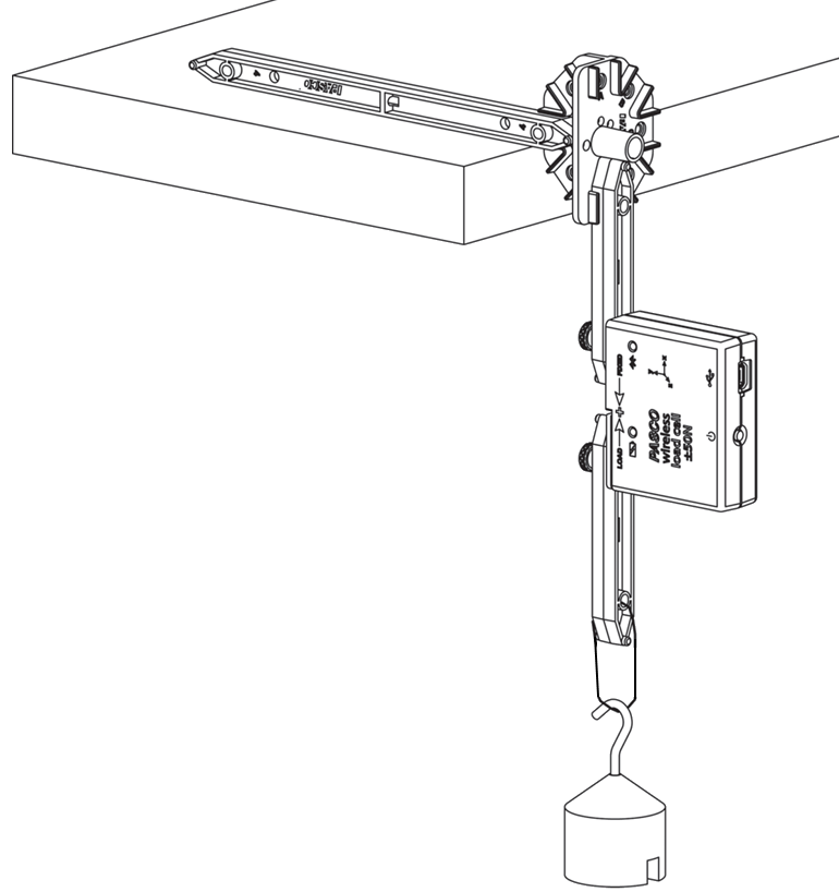
An example calibration fixture, created using PASCO Structures components, is shown in the figure below. Ensure that the loop of string that will hold the 1 kg mass is tied to the LOAD side of the Load Cell.
Important
The calibration fixture in the image below will need to be held in place, either by hand or by mounting a heavy weight on top of the horizontal crossbeam.
Calibration
- Mount the Load Cell on the calibration fixture. Do not attach the 1 kg mass yet.
- Connect the Load Cell to SPARKvue.
- Select Force from the list of available measurements, then select a template to open the Experiment Screen.
-
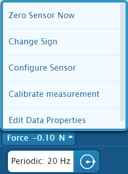
From the Live Data Bar in the bottom left, click on Force (N) and select Calibrate measurement from the menu.
-
Make sure the settings match these values, as shown in the image below:
- Sensor: Wireless Force Sensor
- Measurement: Force (N)
- Calibration Type: 2 point (Adjust Slope and Offset)
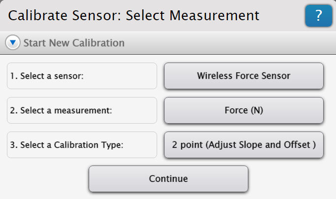
-
Click Continue.
- Hang the 1 kg mass from the string attached to the LOAD side of the Load Cell.
- The force on the sensor is now -9.8 newtons (N). Enter -9.8 into the Standard Value box under Calibration Point 1, then click Set Calibration.
- Remove the mass from the string. The force on the sensor is now 0 N.
-
Enter 0 into the Standard Value box under Calibration Point 2, then click Set Calibration.
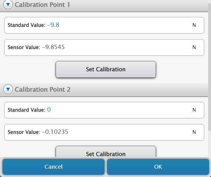
-
Review the new calibration under the New Calibration tab, then click OK.