//control.Node outputs
Control the output devices connected to a //control.Node using specialized blocks.
Speaker
Two blocks are available to control the speaker on a //code.Node. One block sets the speaker frequency and the other simply turns it on (true) or off (false). You can also turn off the speaker by setting the frequency to 0.


Servo motors
Use the set servo block to control positional or continuous rotation servo motors.

-
//control.Node selector
If using more than one //control.Node, select which //control.Node you want to control.
-
Port
Select the port the servo is connected to on the //control.Node.
-
Servo mode
Select angle for standard servos, timed angle (°) to rotate the servo by a specific angle in a specific time, or rotate at speed for continuous rotation servos. You can also use the turn off power option if you do not want the servo to consume power. The servo will not hold its position when turn off power is selected.
-
Value
A positive value rotates the servo counterclockwise and a negative value rotates it clockwise. For angle, enter a value between -90 and 90 degrees. For rotate at speed, enter a value between -100 and 100%. You can also replace this block with one from the Math group.
Note
If timed angle (°) is selected for the mode, two additional fields will appear after the value: a text box in which to enter the time (in seconds) over which the rotation should occur, and a check box labeled Wait for completion. If the box is checked, the code will pause execution until the rotation completes; if it is not checked, the code will continue executing during rotation.

Stepper motors
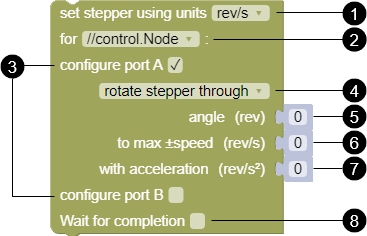
Use the set stepper block to control the High Speed or Low Speed Stepper Motor. You can configure the stepper to rotate continuously or for a specified angle.
Note
The stepper will not rotate if the angle, max speed, or acceleration parameters are set to zero.
-
Units
Select which units you want to use for the angle, max speed, and acceleration.
-
//control.Node selector
If using more than one //control.Node, select which //control.Node you want to control.
-
Port
A single block can be used to configure both Power Out ports simultaneously. Select the box to configure port A, port B, or both.
-
Rotation mode
Select one of the following modes:
-
rotate stepper continuously
In this mode, the stepper rotates until another block changes the motion. Enter a value for max speed to set the rotation speed. Enter a value for acceleration to set the rate that the stepper changes its speed from zero to the max speed.
-
rotate stepper through
In this mode, the stepper rotates for an amount equal to the entered angle. Enter a value for max speed to set the rotation speed. Enter a value for acceleration to set the rate at which the stepper accelerates to the max speed and slows down to a stop.
-
stop
In this mode, the stepper slows down to a stop. Enter a value for the acceleration to set the slow-down rate.
-
-
Angle (through mode only)
Enter an angle for the stepper to rotate then stop. If the Wait for completion box is selected, the program will not move to the next block until the motor completes its rotation.
-
Max speed
Enter the maximum speed the stepper turns. A positive number rotates the counterclockwise and a negative number rotates clockwise.
-
Acceleration
Enter the amount the stepper accelerates when it starts rotating. When using through mode, this value also sets the deceleration when coming to a stop.
Note
High acceleration values may cause jerky movements that make motion less precise. It can also cause the motor to slip and report inaccurate measurements.
-
Wait for completion (through mode only)
Select this box to allow the stepper to complete its rotation before moving to the next block.
The following table lists the allowed range for each measurement by unit. A value entered less than the minimum value will output the minimum value. A value entered larger than the maximum value will output the maximum value.
| Min rev/s | Max rev/s | Min rpm | Max rpm | Min °/s | Max °/s | Min rad/s | Max rad/s | |
|---|---|---|---|---|---|---|---|---|
| Angle | 0 | 68.26 | 0 | 68.26 | 0 | 24570 | 0 | 428.8 |
| Max speed | -2 | 2 | -120 | 120 | -720 | 720 | -12.6 | 12.6 |
| Acceleration | 0 | 6.826 | 0 | 409.6 | 0 | 2457 | 0 | 42.88 |
Grow Light
Use the set grow light block to control the brightness of the blue and red LEDs on the Grow Light. Enter a value between 0 and 10 to set the brightness of the red (R) and blue (B) LEDs.

Power Output Board
Use the set power output block to control devices connected to the Power Output Board. The Power Output Board can control any device that can be powered up to 5 volts with 1 amp of current. The board includes two channels that allows you to connect and control two devices simultaneously. You can connect a device to each channel using either the USB port or the terminals. The power output can be varied when using the terminal connection. Power is provided using pulse width modulation (PWM).

-
//control.Node selector
If using more than one //control.Node, select which //control.Node you want to control.
-
Port
Select the Power Out port the Power Output Board (A or B) is connected to and the Power Output Board channel the device is connected to (CH1 or CH2).
-
Connection
Select whether the device is connected to USB or to the terminal.
Important
Make sure that terminal isn't selected when a USB device is connected. The USB device might get damaged if a power value is set below 100%.
-
Value
- USB: Select
trueto have the power on orfalseto have the power off. You can also replace this block with one from the Logic group. - terminal: Enter a power value between -100 and +100%. The percentage indicates the duty cycle of the PWM signal. A lower percentage corresponds with a lower average voltage. You can also replace this block with one from the Math group.
- USB: Select
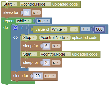
Run uploaded code

The uploaded code block can be used to start or stop code uploaded to the //control.Node. In order to use this block, the code in the Code tool must be different than the code uploaded to the //control.Node.
The following example code uses this block to start and stop uploaded code using a Wireless Light Sensor measurement. The uploaded code starts when you click Start  . When the sensor detects darkness (set at a value less than
 600), the uploaded code stops running for 5 seconds and then starts again. When you click Stop  , the uploaded code also stops.